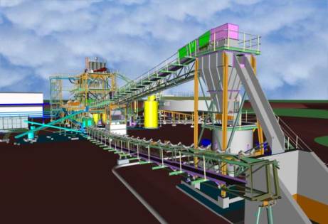
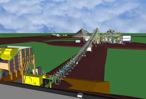
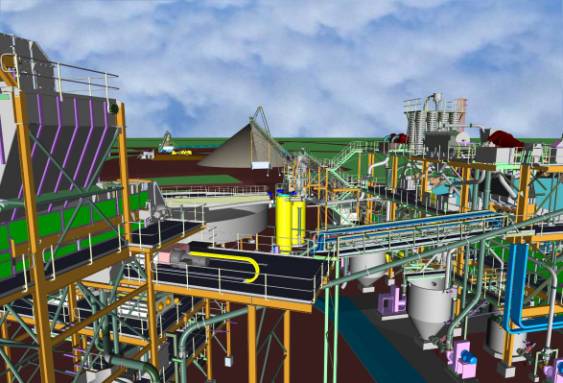
“We knew this would be a big job from
the very start,” says John De Andrade, Principal
modeler for Haald Engineering in Brisbane,
Australia.
Haald Engineering signed a
contract in late 2008 to do the detailed design
for a new coal mine at Cameby Downs, about 275 km
from Brisbane in the southeastern part of
Queensland, Australia. Australia is the world’s
fourth largest coal producer, after China, the US,
and India; Cameby Downs could eventually produce
up to 20 million tons of high-quality “black” coal
per year.
Haald Engineering is experienced
in major mining construction projects, materials
handling, defense and transportation, and others.
Since Haald would handle the entire job, including
mechanical, structural, piping, and concrete
footings De Andrade knew he would use
Pro/ENGINEER.

The Cameby Downs Coal
Mine is expected to eventually produce 20 million
tons of high-quality coal per day, and generate
600 jobs in southeastern
Australia
Two reasons for choosing
Pro/ENGINEER. “We really had two basic reasons
for going with Pro/ENGINEER,” De Andrade says.
“First, it uses true parametric design, which
means we could use a top-down design approach.
With parametric design, once you get the basic
skeletons down, everything becomes associative. So
we always know that if we make a change in one
area, it will be translated to any other modules
or assemblies that are related to it. Because
there were so many interrelated technologies, and
our reviewers included a good number of people, we
knew there would be a lot of modifications along
with way.”
The second reason was the scope
of the project. The site footprint was one
kilometer square, and De Andrade didn’t know of
any other CAD software that could handle a project
that large and still be fully parametric.
“We’ve used other CAD systems
for some jobs,” he says. “But Cameby Downs would
involve huge assemblies, and they couldn’t handle
that.”
Starting with a Skeleton.
The key to designing massive assemblies is to
use a top-down design approach, according to
Haald’s managing director Andrew Reid. DeAndrade
began by creating a top level 3D skeleton to serve
as the framework for all other assemblies. Within
the skeleton they published geometries
that were used to build the five top-level
area assemblies for conveyors, structures,
mechanical equipment, piping, bins and hoppers.
Each of these would have a master assembly
skeleton for the next lower level of assemblies,
and each of those a master to the assemblies below
it.
“We took a top-level skeleton
assembly and built in references and
workpoints that could be published to the
next-level sub-assemblies,” says Reid. “The
references are published geometries from skeletons
that will remain stable and controlled from 1
location—like a certain angle on a conveyor or
pulley locations. Another engineer can then start
working on a sub-assembly module by building
around those references.
“This way, you can get a whole
design team working at the same time on different
assemblies. That’s the best way to do a project
this big and complex.”

The key to designing
massive assemblies is to use a top-down design
approach
The other key was using a fully
parametric CAD application, De Andrade says. “Our
client might look at the entire assembly model of
the main process building and say, “Can you lift
the floor level by a meter?” With Pro/ENGINEER,
the answer is yes, because all related changes
will automatically propagate to the sub-assemblies
below.
“It’s important that the
software be fully parametric, too,” De Andrade
says. “I can modify a dimension in the skeleton,
say the height of a conveyor head pulley or
building column centers, then regenerate the model
and have every related subassembly model update
and all the associated drawings update
automatically.
“We’ve seen systems that will
go halfway—they might be able to extend the height
of columns on a trestle, but they couldn’t
automatically widen the column spacings—you’d have
to go and move each column manually.”
For the project Haald used
Pro/ENGINEER Expert Framework Extension (EFX) for
designing the structural framework and the piping
layouts of the buildings. Pro/ENGINEER EFX
contains a large library of sections, connections,
joints, stairs, and other parts, and it’s fully
parametric, so it propagates any upper-level
changes to sub-assembly structures.

Haald used
Pro/ENGINEER Expert Framework Extension (EFX) for
designing the structural framework and the piping
layouts
Help with the client.
The parametric software also helped Haald keep
its client project team up to date on the design’s
progress—important in a project that’s visible to
the community and the government as well as to its
investors.
“We had reviews with a dozen
people or more pretty regularly,” De Andrade says.
“We’d be able to show a particular equipment
assembly and even let the client take a virtual
walkthrough to check ergonomics and maintenance
access. The client might ask for more clearance
around a certain piece of equipment, and we’d make
the change on the spot, regenerate the model, and
it would show how that change affected everything
else, including piping and chute work—everything.
“Without Pro/ENGINEER, it might
take all day to regenerate a model like that—and
the client would be less than impressed.”
Haald also set up a client
extranet site and uploaded the assembly models at
the end of each week for client
inspection.
Thanks to the efforts of the
Haald team the design project was
completed in 2009 and holds more total
parts than De Andrade has wanted to count. He will
say that the five top-level assemblies alone have
more than 80,000 unique parts, more than enough,
he says, to bring most CAD software to its
knees.
Haald
Engineering, based out of Brisbane, Australia,
offer specialized mechanical engineering
services, including implementation, design,
and analysis. They serve a broad range of
industries from mining, defense, sugar factories
and agriculture to defense, energy and
transportation.
Related
Information:
Was this article interesting?
Let
us know.
![]()
![]()